Tutorial: a 2.4 GHz IFA from scratch
You draw a printed inverted-F antenna on a 30 × 40 mm ground plane, simulate it, tune it to 2.45 GHz and match it to 50 Ω. The antenna is the same as the template Printed IFA (2.4 GHz): open it with File > New from template... to compare at any step. The template has the arm already tuned (21.1 mm); here you start from 17 mm and tune it yourself in step 3.
About 30 minutes. All sizes are in millimetres; y goes up and the top edge of the ground plane is at y = 0.
1. Draw the antenna
The board and the stackup
- File > New. The new project has a two-layer board, Top and Bottom.
- In Board & simulation, set the dielectric to 0.8 mm, εr 4.4, tanδ 0.02 (FR-4).
The board outline and the ground planes
The Add, Duplicate and Remove tools are in the toolbar on the left of the Geometry view. Each new shape appears in the Shapes tab: type its numbers there, and give it a name (double-click the cell).
| Name | Layer | Kind | X | Y | Length | Width |
|---|---|---|---|---|---|---|
| Board | Board | Rectangle | 0 | -17.1 | 30 | 45.8 |
| GroundTop | Top | Rectangle | 0 | -20 | 30 | 40 |
| GroundBottom | Bottom | Rectangle | 0 | -20 | 30 | 40 |
X and Y are the centre of a rectangle, Length its size along x and Width its size along y. For GroundBottom, select GroundTop, click Duplicate and change the name and the layer. The board shape sets the outline of the dielectric: here it leaves 5.8 mm above the ground for the antenna.
The short, with Join
- Add a rectangle: name Short, layer Top, X -13.5, Y 6, Length 0.8, Width 4.8. It floats above the ground.
- Click GroundTop in the Geometry view (the item that stays), then Ctrl+click Short.
- Click Join. Short moves down until it touches the ground edge exactly: it now runs from y = 0 to y = 4.8.
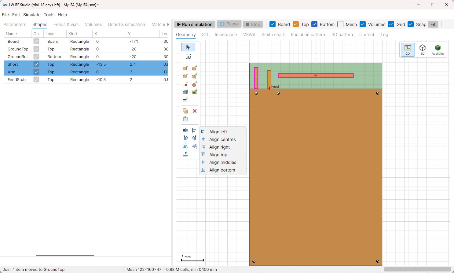
The arm, with Align
- Add a rectangle: name Arm, layer Top, X 0, Y 3, Length 17, Width 0.8.
- Select Short, then Ctrl+click Arm.
- Open the Align button and choose Align left: the left edges line up on the leftmost one, the short's (x = -13.9).
- Again Align > Align top: the arm goes up to the top of the short (y = 4.8). Short and arm now form the inverted L.
The feed stub
- Add a rectangle: name FeedStub, layer Top, X -10.5, Y 2, Length 0.8, Width 4.3. It is 3 mm to the right of the short.
- Select Arm, Ctrl+click FeedStub, Align > Align top. The stub hangs from the arm and stops 0.5 mm above the ground: this gap is where the feed goes.
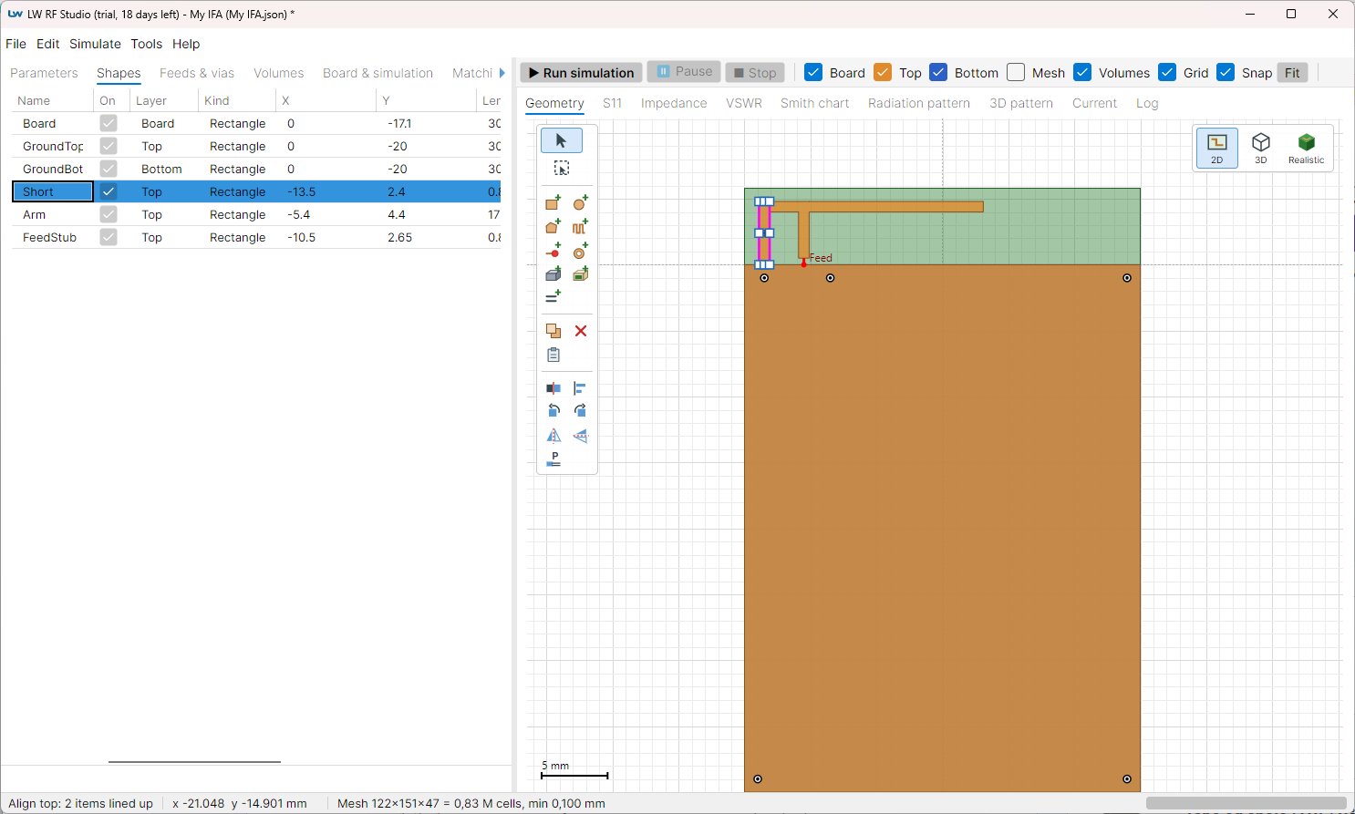
The Shapes tab now shows the same numbers as the template: Short at (-13.5, 2.4), Arm at (-5.4, 4.4), FeedStub at (-10.5, 2.65).
Right-click a shape to turn it by 90°; the Rotate and Mirror tools turn or flip a whole selection. A small cross shows the origin of the selected shapes.
The feed and the vias
In Feeds & vias, click Add a feed port and set: mode In-plane, layer Top, X -10.5, Y 0, X2 -10.5, Y2 0.5, 50 Ω. The port bridges the gap between the ground edge and the stub. Then add five vias from Top to Bottom, to tie the two ground planes together:
| X | Y |
|---|---|
| -13.5 | -1 |
| -8.5 | -1 |
| 14 | -1 |
| -14 | -39 |
| 14 | -39 |
Save the project (Ctrl+S). Check it against the template: both should look the same in the 2D and 3D views.
2. A first simulation in Fast mode
- In Board & simulation, set Start frequency 1.8 GHz, Stop frequency 3.2 GHz and Pattern frequency 2.45 GHz.
- Choose the preset Fast (estimate). It uses a coarser mesh and stops earlier: several times faster, and the resonance is within a few percent of the accurate result. That is enough to see where the antenna is.
- Click ▶ Run simulation (F5). The log shows the progress, and the engine used: the GPU when the PC has an NVIDIA card.
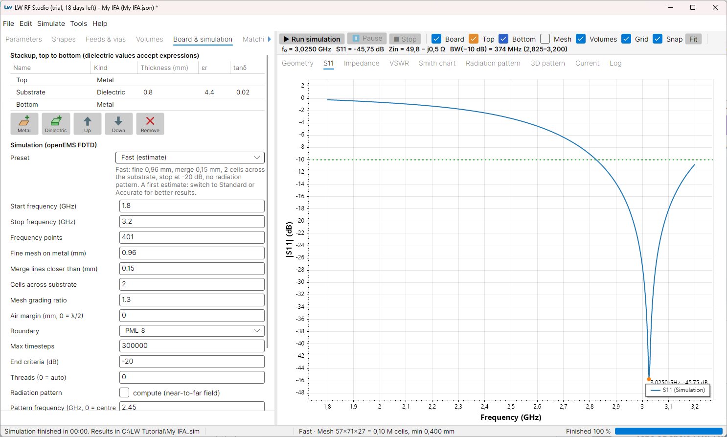
When it ends, the line under the toolbar gives the resonance f0, S11 and the impedance there, and the −10 dB band. Look at the S11 and Smith chart tabs. With a 17 mm arm, the antenna resonates at about 3.03 GHz: too high, so the arm is too short. A longer arm lowers the resonance.
3. Tune the arm to 2.45 GHz
The tuning moves a parameter, so the arm length must be one first.
- Select Arm and click Parameters from shapes (the last tool of the toolbar). Tick Size only and click Create parameters. The arm now uses the parameters Arm_L and Arm_W (see the Parameters tab).
- X is the centre of the arm: when its length changes, both ends move. To keep the left end on the short, type -13.9 + Arm_L/2 as the arm's X in the Shapes tab. The drawing does not change.
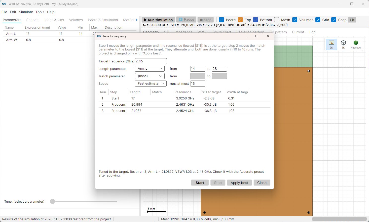
- Simulate > Tune to frequency...: target 2.45 GHz, length parameter Arm_L, from 14 to 28 mm (or give Arm_L a Min and a Max in the Parameters tab first), speed Fast estimate. Click Start.
- Each step is a simulation; the window shows the resonance of each run. Here three runs are enough: Arm_L = 21.09 mm puts the resonance at 2.45 GHz. Click Apply best, then Close.
In the Parameters tab, the Tune slider under the table changes a parameter by hand: select Arm_L, move the slider and watch the arm in the Geometry view, then run again. Give a parameter a Min and a Max to set the range of the slider.
4. The accurate simulation
- In Board & simulation, choose the preset Accurate (final): a finer mesh on the copper and a lower end criterion.
- Run the simulation again. It takes longer, much less with the GPU engine.
- Look at the results: S11, Impedance, VSWR, Smith chart, the Radiation pattern with the directivity and the efficiency, the 3D pattern and the Current on the copper.
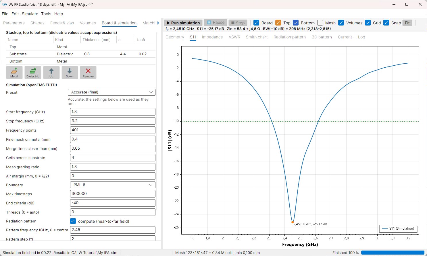
With the tuned arm, the accurate simulation gives f0 = 2.451 GHz, S11 = −25 dB and a −10 dB band of 298 MHz (2.32 to 2.62 GHz): the Fast estimate was close.
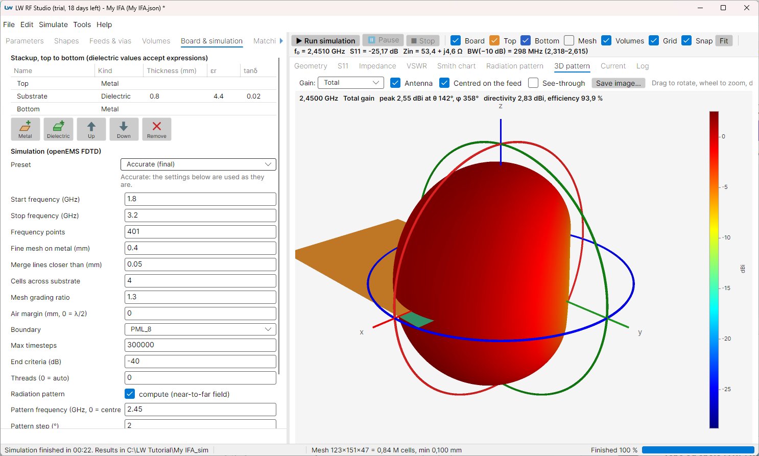
When the resonance has moved from the Fast result, tune once more, now with the Standard speed. File > Export report as PDF... keeps the geometry and the results together.
5. Final tuning with Matching
The resonance is at 2.45 GHz, but the impedance there is not exactly 50 Ω. A small L/C network between the radio and the antenna corrects it, without changing the copper.
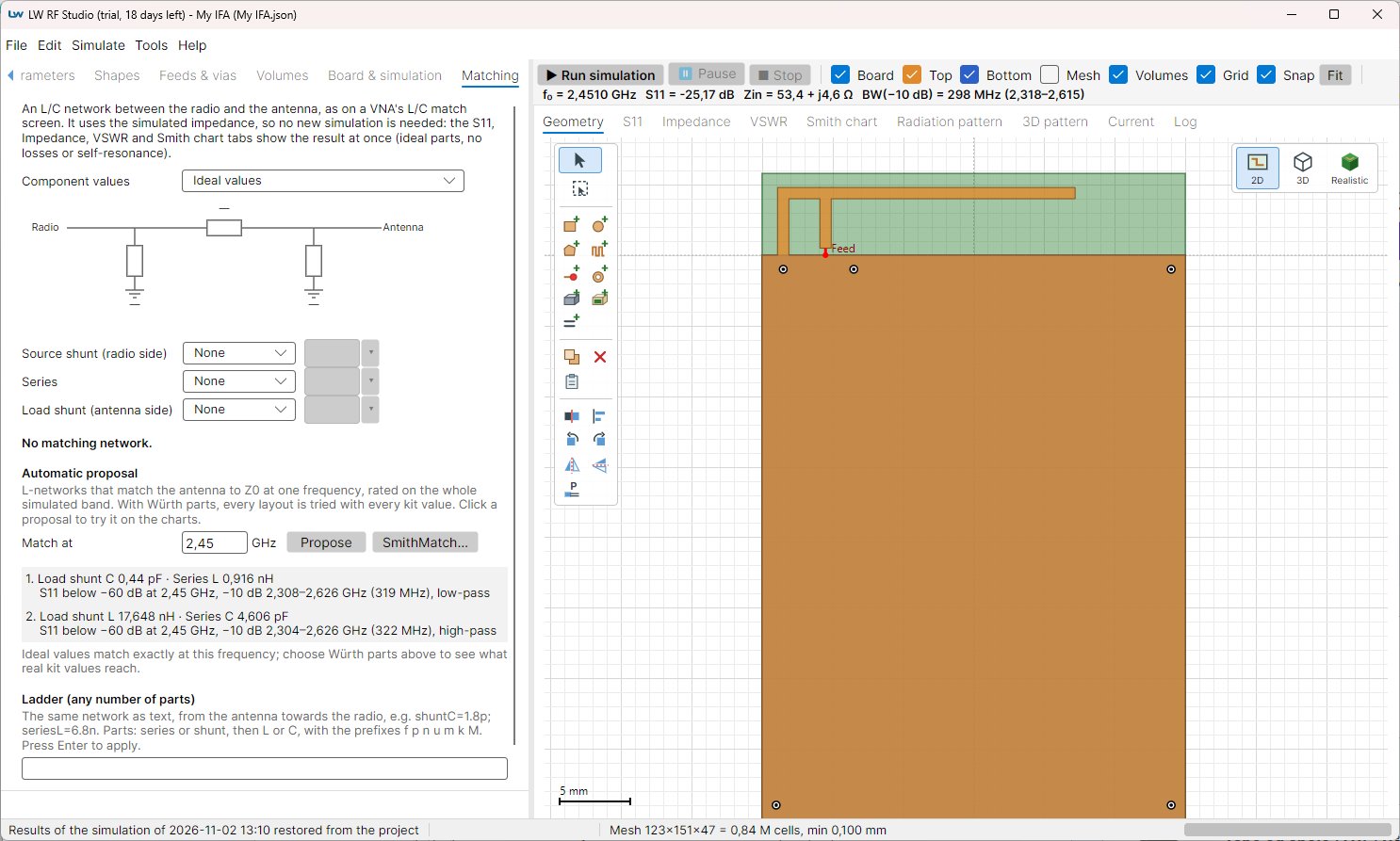
- Open the Matching tab (next to Board & simulation; when the panel is narrow, the small arrow at the end of the tab row brings it into view).
- Under Automatic proposal, set Match at 2.45 GHz and click Propose. The L-networks that match the antenna are listed, rated on the whole band, with Würth Elektronik part numbers.
- Choose one: S11, VSWR and the Smith chart show the antenna with the network, next to the antenna alone.
- For a finer choice, click SmithMatch...: move the parts on the Smith chart and see the band change, with the parasitics of the real parts.
Put the network on the board, measure it with a VNA, and load the measurement with Simulate > Load reference S11 to compare it with the simulation.
Next
Import your own board (File > Import PCB board) and click on the board to place the feed, or start from another template: MIFA, meander, patch, Yagi. The user manual describes every tab. A question? Use the contact form.